Explore using the Arduino to generate a pseudo-analog output voltage with Pulse-width Modulation (PWM) and Frequency Modulation. Develop a creative enclosure for one of the circuits.
Lab Objectives:
- Use PWM to drive a servo motor
- Use
tone()to generate a frequency
Lab 6 Resources:
Part 1: Servo Motor Control with an Arduino
Supplies for Part 1
- Solderless Breadboard and hookup wire
- Arduino microcontroller module & USB connector
- 10Kohm resistors
- Flex sensor (or a different form of variable resistor)
- RC Servomotor
Setup the Circuit
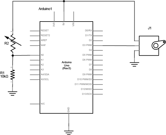
Pick any analog input and connect it to Analog pin 0 as you did in Lab 5 covered previously.
When you attach the servo, you’ll need a row of three male headers to attach it to a breadboard. You may find that the pins don’t stay in the servo’s connector holes. Put the pins in the servo’s connector, then push them down on a table gently. They will slide up inside their plastic sheaths, and fit better in your servo’s connector. You may also try jumper wires. Related video: Connect the Servo
Program the Microcontroller
First, find out the range of your sensor by using analogRead() to read the sensor and printing out the results (like you did in Lab 5).
Then, map the result of the analog reading to a range from 0 to 179, which is the range of the sensor in degrees. Store the mapped value in a local variable called servoAngle.
Finally, add the servo library at the beginning of your code, then make a variable to hold an instance of the library, and a variable for the servo’s output pin. In the setup(), initialize your servo using servo.attach(). Then in your main loop, use servoAngle to set the servo’s position.
// include the servo library

// creates an instance of the servo object to control a servo
// declare the control pin for servo motor, call it servoPin

void setup() {
  // initialize serial communications
  // attach the servo object to the servoPin
}

void loop() {
  // read the analog input
  // print it to the serial monitor

  // make a new int called angle - use the map() function to map the range of your sensor to the range of the servo (which is 0 to 179)

  // move the servo using the angle from the sensor with the servo write() function
}
Related Video: Code for the Servo & Turn the Servo
Part 2: Tone Output Using An Arduino
Supplies for Part 2
- Solderless Breadboard and hookup wire
- Arduino microcontroller module & USB connector
- 100 ohm resistors
- photocell (or a different form of variable resistor)
- 8 ohm speaker
Why not use AnalogOut?
When you use analogOut() to create pulsewidth modulation (PWM) on an output pin, you can change the on-off ratio of the output (also known as the duty cycle) but not the frequency. If you have a speaker connected to an output pin running analogOut(), you’ll get a changing loudness, but a constant tone. To change the tone, you need to change the frequency. The tone() command does this for you.
Setup the Circuit
Connect two photoresistors to analog pin 0 in a voltage divider circuit as shown below. The 8-ohm speaker connects to pin 8 of the Arduino. You can use any digital I/O pin if you don’t like 8. The other end of the speaker connects to ground. Related video: Connect the Speaker
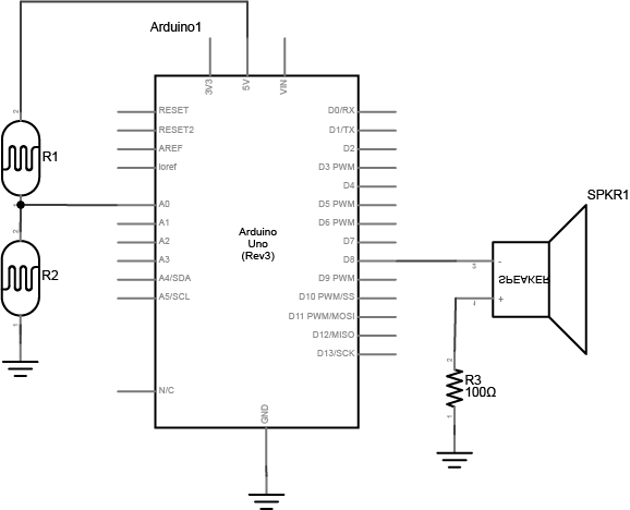
NOTE: this sensor circuit is not the normal way of connecting an analog input. There is no fixed resistor. The two photocells act as a voltage divider together, so you can change the value of the analog in by covering either one. if you are using variable resistors that can both go to 0 ohms, you should connect a fixed resistor in series from the junction of the two resistors to the input, to avoid a short.
Program the Microcontroller
First, check the sensor input range (the way you did in Lab 5). Note what sensor range you’re getting.
void setup() {
  // initialize serial communications
}

void loop() {
  // read the analog input
  // print it to the serial monitor
}
Next, play tones! Write a program to read the analog input and map the result to a range from 100 to 1000. Store the result in a local variable called frequency. This will be the frequency you play on the speaker. Then use the tone() command to set the frequency of the speaker on pin 8.
void setup() {
    // nothing else to do here
}

void loop() {
   // read the analog input
   // map the results from the sensor reading's range to the desired pitch range, call this frequency (hint: the data type is a float)
   // play a tone() for 10ms at your frequency
}
Once you’ve uploaded this, move your hands over the photocells, and listen to the frequency change. It will change from 100 Hz to 1000 HZ, because that’s what you set in the map() command. If you want to change the frequency range, change those two numbers. See if you can get it to play a little tune.
Part 3: Creative Enclosure
Get Creative with an Enclosure! For either Part 1 or Part 2 (choose one), design an interactive object around the circuit. How can you apply these technologies in a creative way?
Here’s a few cool servo motor projects for inspiration:
- You can play drums like in this project by Nick Yulman.
- You can build a frisking machine like in this project by Sam Lavigne and Fletcher Bach.
- If you’ve got 800 or so of them and a lot of time, you can build a wooden mirror like this project by Daniel Rozin
Lab 6 is due before class on Thursday February 23rd
Your blog response should include a schematics of both circuits, details about your enclosure, a clear video of your working circuits (for both part 1 and part 2) and a brief description of what the circuit does and how you made it. Submit a link to your blog post on Edmodo.