Lab 5 - Analog In
Lab Objectives:
- Read Analog sensor values using
analogRead() - Print sensor values to the serial monitor
- Use
analogWriteon a PWM pin - Learn to fit an analog input reading into a single byte using division or the
map()function
Lab 5 Resources:
- Videos: Analog Input 1 and Analog Input 2
- Adafruit’s guide to Forse Sensitive Resistors (FSR)
Analog Input and Output Lab:
For this lab you will need the following parts:
- Solderless Breadboard and hookup wire
- Arduino microcontroller module & USB connector
- LEDs of different colors
- 560 ohm (or anything from 220 to 1K) and 10 Kilohm resistors
- 10Kohm potentiometer
- 2 Variable Resistors
Part 1: Potentiometer
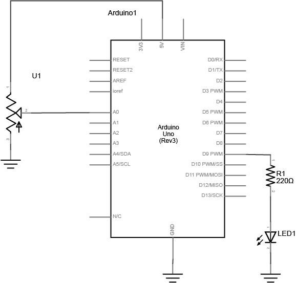
Build a circuit with a potentiometer as the input, and an LED as the output. Use analogRead() for the incoming potentiometer value, and analogWrite() to set the brightness of the LED.
Setup the breadboard
Connect a potentiometer to analog in pin 0 of the module, and an LED and a resistor to digital pin 9:
Program the Module
First, establish some global variables -
// declare a global constant to give the LEDs pin number a name

// declare an int to hold the value returned by the potentiometer, use analogValue

// declare int for brightness value - to use for writing PWM to LED
In the setup() method -
void setup() {

    // initialize serial communications at 9600 bps

    // declare the led pin as an output:

}
In the main loop - read the analog value using analogRead() and put the result into the variable that holds the analog value. Then divide the analog value by 4 to get it into a range from 0 to 255. Then use the analogWrite() command to face the LED. Then print out the brightness value.
void loop() {

	// read value from the pot and put results into analogValue

	// get analogValue it to fit into a byte - this is the brightness

	// PWM the LED with the brightness value

	// print the brightness calue back to the serial monitor
}
When you run this code, the LED should dim up and down as you turn the pot, and the brightness value should show up in the serial monitor.
Part 2: Other Variable Resistors (going a bit further…)
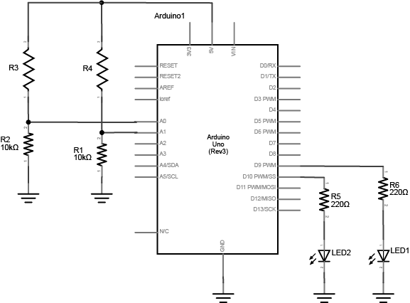
Build a circuit with at least 2 different variable resistors that output brightness values to two different colored LEDs
Build two voltage divider circuits that connect to A0 and A1, using variable resistors for R3 and R4 (try a photocell or an FSR). To both pin 9 and 10, connect a resistor + LED. Use different colors for LED1 and LED2.
In Part 1, you used a potentiometer as input which always gives the full range of analog values, which is 0 to 1023. You can divide this value by 4 to get a range of 0 to 255, which is the full output range of the analogWrite() command.
A voltage divider circuit, on the other hand, can’t give you the full range. The fixed resistor in the circuit limits the range. You’ll need to modify the code or the resistor if you want a different range.
Use the serial monitor to find your sensor range. Then use the map() function to map the actual range that the sensor gives as input to the range that the LED needs as output.
Lab 5 is due before class on Thursday September 22nd
Your blog response should include a clear video of both of your working circuits and a brief description of what you made. Submit a link to your blog post on Edmodo.