Lab 5
In this lab you will explore motors and build circuits using servo, DC and stepper motors. You will use an Arduino to generate a pseudo-analog output voltage (PWM) to control a servo motor, and will learn to drive DC and stepper motors using an H-Bridge.
Lab Objectives:
- Use PWM to drive a servo motor
- Use an H-bridge to drive a DC motor
- Drive a stepper motor with an H-bridge
Lab 5 Resources:
- Analog Output – Motor Control
- Analog Output – Servo
- DC Motors: The Basics
- Tom Igoe’s Notes on Steppers
- Controlling Stepper Motors
- H-Bridges (video)
- All About Steppers (video)
- Controlling a Unipolar Stepper Motor (video)
Part 1: Servo Motor Control
Supplies for Part 1
- Solderless Breadboard and hookup wire
- Arduino microcontroller module & USB connector
- 10Kohm resistors
- Flex sensor (or a different form of variable resistor)
- RC Servomotor
Build the Circuit
Pick any analog input and connect it to Analog pin 0 as you did in Lab 5 covered previously.
When you attach the servo, you’ll need a row of three male headers to attach it to a breadboard. You may find that the pins don’t stay in the servo’s connector holes. Put the pins in the servo’s connector, then push them down on a table gently. They will slide up inside their plastic sheaths, and fit better in your servo’s connector. You may also try jumper wires. Related video: Connect the Servo

Program the Microcontroller for Servo Control
First, find out the range of your sensor by using analogRead() to read the sensor and printing out the results (you did this in a previous lab).
Include the servo library in your code. Then, map the result of the analog reading to a range of 0 to 179, which translates the sensor range to a degree for the servo motor. Store this mapped value in a local variable, perhaps called servoAngle.
Finally, add the servo library at the beginning of your code, then make a variable to hold an instance of the library, and a variable for the servo’s output pin. In the setup(), initialize your servo using servo.attach(). Then in your main loop, use servoAngle to set the servo’s position.
// include the servo library

// creates an instance of the servo object to control a servo
// declare the control pin for servo motor, call it servoPin

void setup() {
  // initialize serial communications
  // attach the servo object to the servoPin
}

void loop() {
  // read the analog input
  // print it to the serial monitor

  // make a new int called angle - use the map() function to map the range of your sensor to the range of the servo (which is 0 to 179)

  // move the servo using the angle from the sensor with the servo write() function
}
Related Video: Code for the Servo & Turn the Servo
Part 2: DC Motor Control
In this next part of the lab, you’ll learn how to drive a DC motor. You will incorporate an H-Bridge which will enable you to write code to change the direction of the motor.
To control a DC motor to turn in both directions, you need to be able to reverse the direction of the current supply to the motor. The easiest way to do this is using an H-bridge circuit.
Supplies for Part 2
- Solderless Breadboard and hookup wire
- Arduino microcontroller module & USB connector
- Switch
- 10Kohm resistors
- H-Bridge
- DC Motor
- 9V Power Supply (or battery - although the motor will drain a battery fast)
Build the Circuit
First, add a Digital Input (a switch) - connect this switch to digital input 2 on the Arduino. Next, wire the H-Bridge and the DC motor. Lastly, add an external power supply to drive the motor - you will power the H-bridge from the VIN pin on your Arduino.

How your H-bridge works
The L293NE/SN754410 is a very basic H-bridge. It has two bridges, one on the left side of the chip and one on the right, and can control 2 motor coils. It can drive up to 1 amp of current, and will operate between 4.5V and 36V. The small DC motor you are using in this lab can run safely off a low voltage so this H-bridge will work just fine.

The H-bridge has the following pins and features:
- Pin 1 (1,2EN) enables and disables our motor whether it is give HIGH or LOW
- Pin 2 (1A) is a logic pin for our motor (input is either HIGH or LOW)
- Pin 3 (1Y) is for one of the motor terminals
- Pin 4-5 are for ground
- Pin 6 (2Y) is for the other motor terminal
- Pin 7 (2A) is a logic pin for our motor (input is either HIGH or LOW)
- Pin 8 (VCC2) is the power supply for our motor, this should be given the rated voltage of your motor
- Pin 9-11 are unconnected as you are only using one motor in this lab
- Pin 12-13 are for ground
- Pin 14-15 are unconnected
- Pin 16 (VCC1) is connected to 5V
If your motor can run on 5V and less than 500mA, you can use the Arduino’s 5V output, otherwise you will need to use an external power supply. Most motors require a higher voltage and higher current draw than this, so you will need an external power supply.
Safety Warning: Running a motor at a voltage much lower or much higher than what it’s rated for could potentially damage or permanently destroy your motor. When the motor doesn’t spin, the voltage is too low. When the motor runs hot, or sounds like it’s straining, the voltage is too high.
Program the Microcontroller
First set up constants for the switch pin, the two H-bridge pins, and the enable pin of the H-bridge. Use one of the analogWrite pins (3,5,6,9,10, or 11) for the enable pin.
const int switchPin = 2;    // switch input
const int motor1Pin = 3;    // H-bridge leg 1 (pin 2, 1A)
const int motor2Pin = 4;    // H-bridge leg 2 (pin 7, 2A)
const int enablePin = 9;    // H-bridge enable pin
In the setup(), set all the pins for the H-bridge as outputs, and the pin for the switch as an input. Then set the enable pin high so the H-bridge can turn the motor on.
void setup() {
    // set the switch as an input:

    // set all the other pins you're using as outputs:

    // set enablePin high so that motor can turn on:

}
In the main loop() read the switch. If it’s high, turn the motor one way by taking one H-bridge pin high and the other low. If the switch is low, reverse the direction by reversing the states of the two H-bridge pins.
void loop() {
    // if the switch is high, motor will turn on one direction

    	// set leg 1 of the H-bridge low
	// set leg 2 of the H-bridge high

    // else (which means the switch is low), motor will turn in the other direction

    	// set leg 1 of the H-bridge high
	// set leg 2 of the H-bridge low
}
Once you’ve seen this code working, try modifying the speed of the motor using the analogWrite() function. Use analogWrite() on the enable pin of the motor, and see what happens as you change the value of the analogWrite().
Part 3: Stepper Motor Control
Stepper motors have multiple coils in them, so that they can be moved in small increments or steps. Stepper motors are typically either unipolar or bipolar, meaning that they have either one main power connection or two. Whether a stepper is unipolar or bipolar, however, you can control it with an H-bridge. This lab shows you how to set up a unipolar stepper motor using an H-Bridge. You can also use the same control circuit with a bipolar motor.
Supplies for Part 2
- Solderless Breadboard and hookup wire
- Arduino microcontroller module & USB connector
- H-Bridge
- Stepper Motor (unipolar)
- 9V or 12V Power Supply
Setup the Circuit
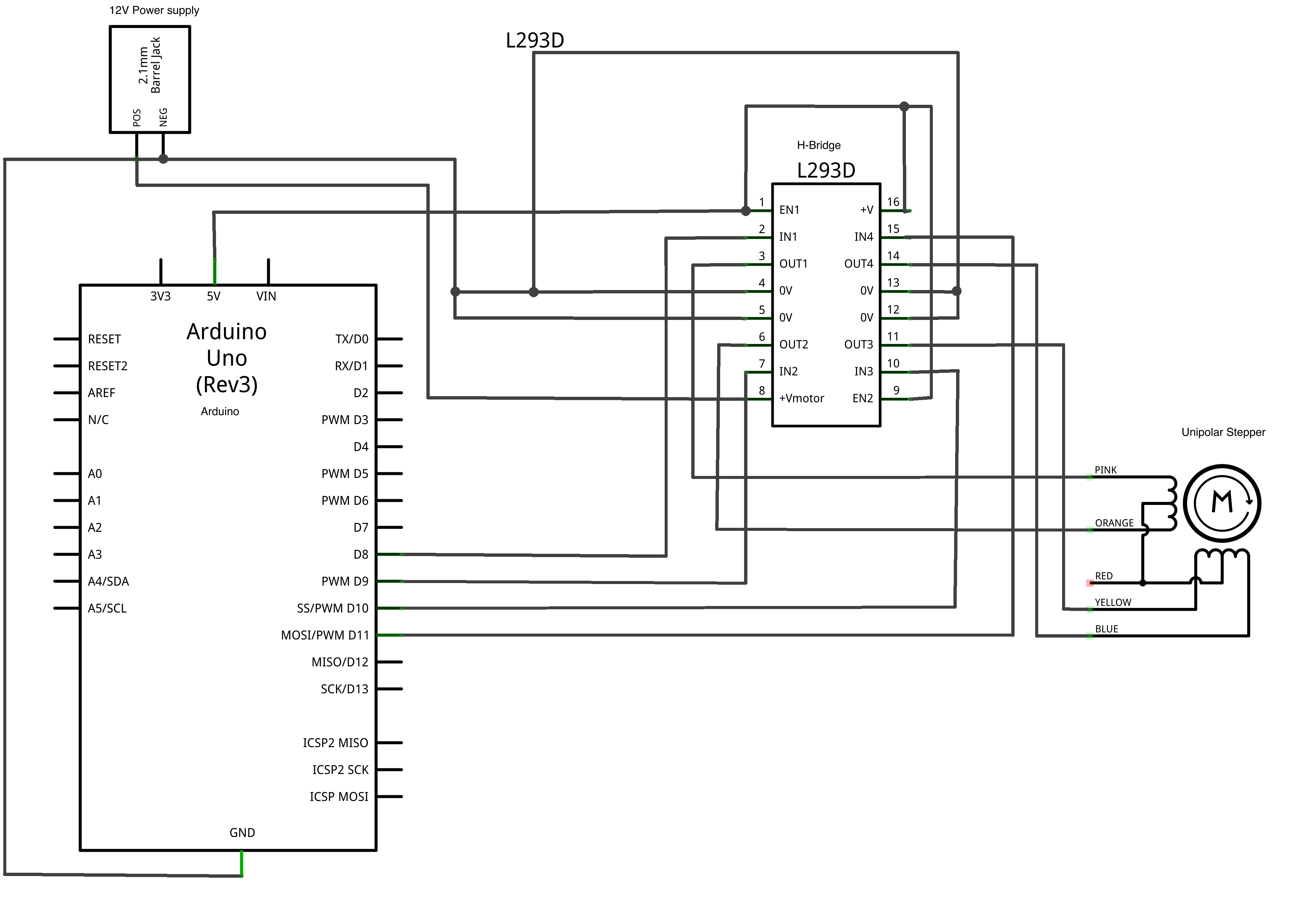
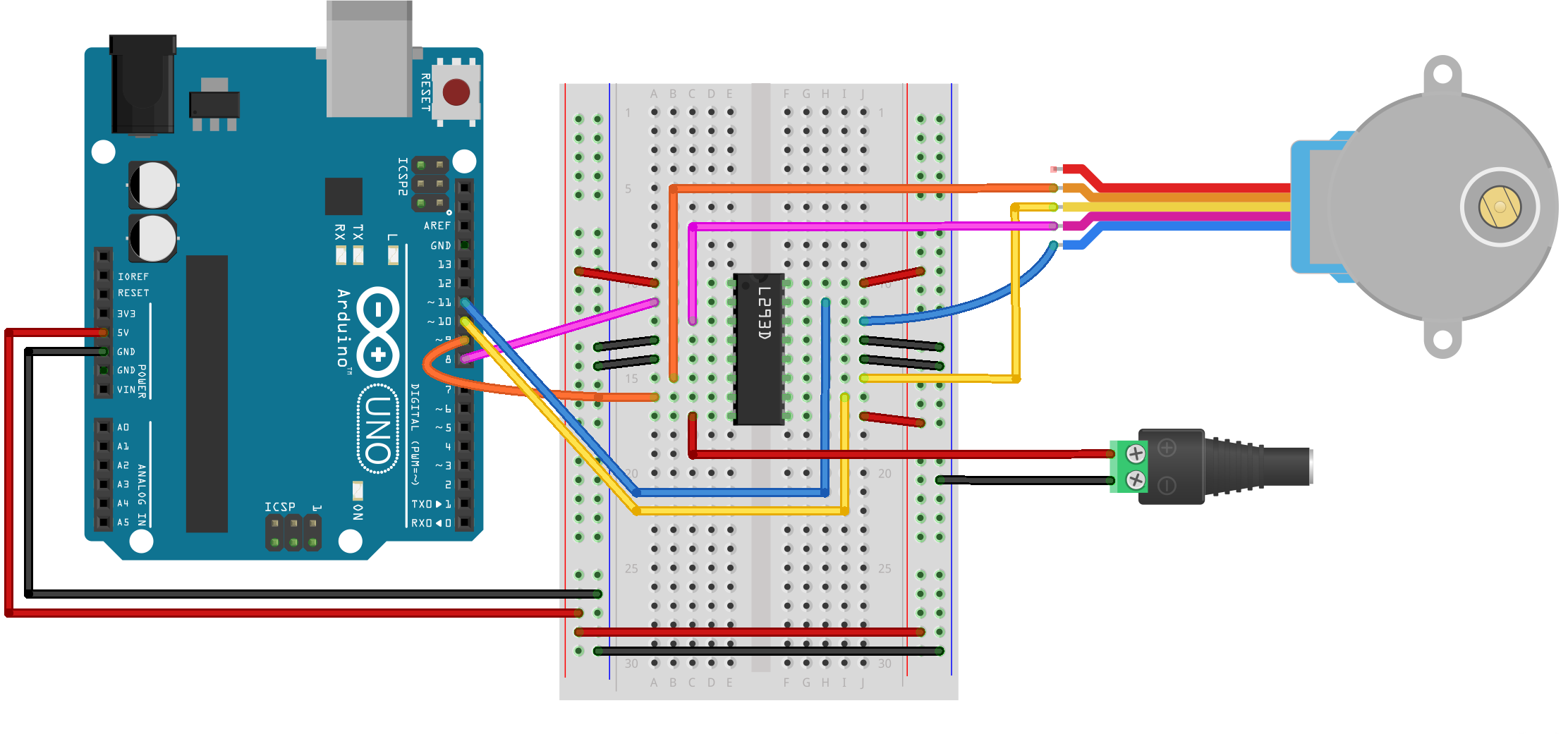
Program the Microcontroller
Program the microcontroller to run the stepper motor through the H-bridge using the stepper library.
Make the stepper move exactly one whole revolution at a time. The number of steps per revolution will depend on your individual stepper, so check the data sheet for the number of steps per revolution, you may need to adjust this number.
Use the Arduino Stepper Library as a reference.
Also, there is helpful code on this stepper revolution example.
Lab 5 is due before class on Thursday April 12th
Your blog response should be structured in 3 parts, one for each part of the lab. Be sure to title each section and include a clear video of your working circuit, a schematic diagram, a written description of what you made, and all of your code either embedded with GitHub Gist or linked to on Github. Submit a link to your blog post on Canvas.