Lab 3
This lab explores analog input and output using variable resistors. You will learn to read sensor values to the serial monitor and utilize pulse width modulation (PWM) and frequency modulation to affect outputs.
Objectives
- Read Analog sensor values using
analogRead() - Print sensor values to the serial monitor
- Use
analogWrite90on a PWM pin to dim an LED - Learn to fit an analog input reading into a single byte using the
map()function - Use frequency modulation with the
tone()command to to generate sounds
Resources
- Videos: Analog Input 1 and Analog Input 2
- Adafruit’s guide to Forse Sensitive Resistors (FSR)
- Analog Output - Tone
Part 1: Potentiometers
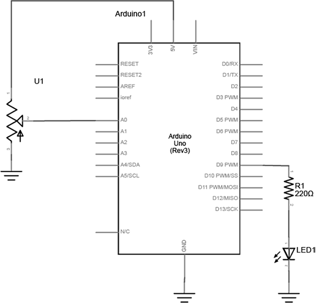
Build a circuit with a potentiometer as the input, and an LED as the output. Use analogRead() for the incoming potentiometer value, and analogWrite() to set the brightness of the LED.
Setup the breadboard
Connect a potentiometer to analog in pin 0 of the module, and an LED and a resistor to digital pin 9.
Program the Module
First, establish some global variables at the top of the program -
	// declare a global constant
	// give the LED pin numbers a name

	// declare an int to hold the pot value

	// declare int for brightness value
	// used for writing PWM to LED
In the setup() method -
	void setup() {

	    // initialize serial

	    // set led pin as an output

	}
In the main loop - read the analog value using analogRead() and put the result into the variable that holds the analog value. Then divide the analog value by 4 to get it into a range from 0 to 255. Then use the analogWrite() command to face the LED. Finally, print out the brightness value to the serial monitor.
	void loop() {

		//read value from the pot
		//put results into analogValue

		//fit analogValue into a byte
		//this is the brightness

		//PWM the LED with the
		//use brightness value

		//print brightness to serial monitor
	}
When you run this code, the LED should dim up and down as you turn the pot, and the brightness value should be printed to the serial monitor.
Part 2: Other Variable Resistors
Build a circuit with at least 2 different variable resistors that output brightness values to two different colored LEDs. You should not use a potentiometer for this part.
Build two voltage divider circuits that connect to A0 and A1, using variable resistors for R3 and R4 (try a photocell or an FSR). To both pin 9 and 10, connect a resistor + LED. Use different colors for LED1 and LED2.
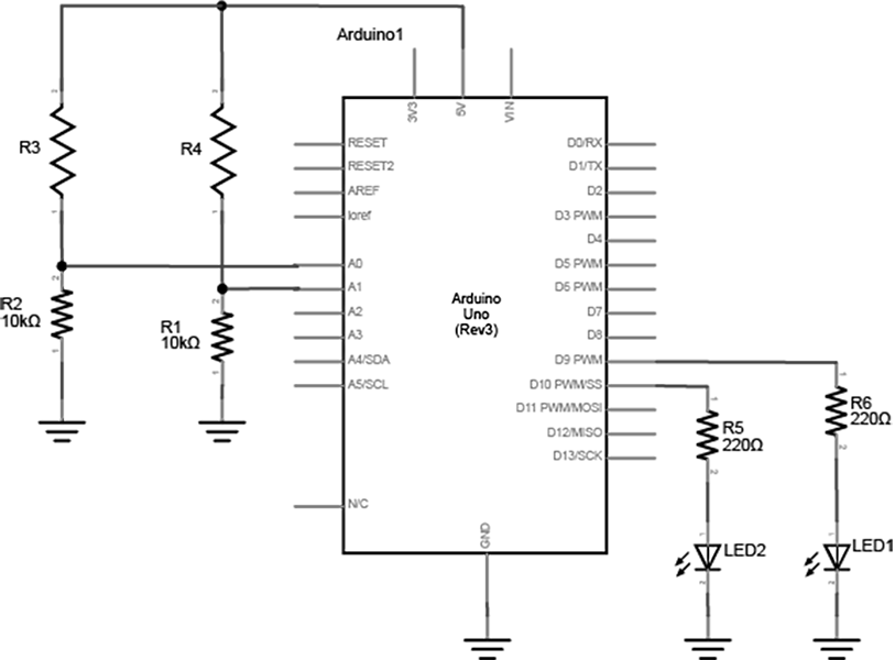
The circuit above works for any variable resistor. It’s called a voltage divider. There are two voltage dividers, one on analog in 0 and one on analog in 1. The fixed resistor in each circuit should have the same order of magnitude as the variable resistor’s range. For example, if you’re using a flex sensor with a range of 50 – 100 kilohms, you might use a 47Kohm or a 100Kohm fixed resistor. If you’re using a force sensing resistor that goes from infinity ohms to 10 ohms, but most of its range is between 10Kohms and 10 ohms, you might use a 10Kohm fixed resistor.
In Part 1, you used a potentiometer as input which always gives the full range of analog values, which is 0 to 1023. You can divide this value by 4 to get a range of 0 to 255, which is the full output range of the analogWrite() command.
A voltage divider circuit, on the other hand, can’t give you the full range. The fixed resistor in the circuit limits the range. You’ll need to modify the code or the resistor if you want a different range.
Use the serial monitor to find your sensor range. Then use the map() function to map the actual range that the sensor gives as input to the range that the LED needs as output.
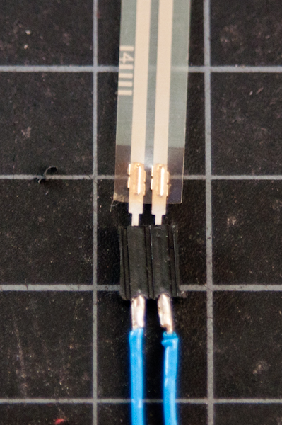
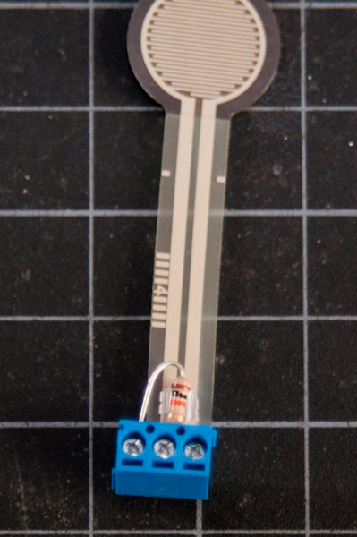
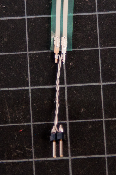
A Note on soldering sensor leads - Flex sensors and force-sensing resistors melt very easily, so unless you are extremely quick with a soldering iron, it’s risky to solder directly to their leads (you run the risk of ruining the component). Here are three better solutions:
- Use female to male jumper cables
- Use screw terminals (if you have a row of three you can attach the fixed resistor as well)
- Use wire wrapping wire and a wire wrapping tool
Part 3: Tone Output
Connect two photoresistors to analog pin 0 in a voltage divider circuit as shown below. The 8-ohm speaker connects to pin 8 of the Arduino. You can use any digital I/O pin if you don’t like 8. The other end of the speaker connects to ground.
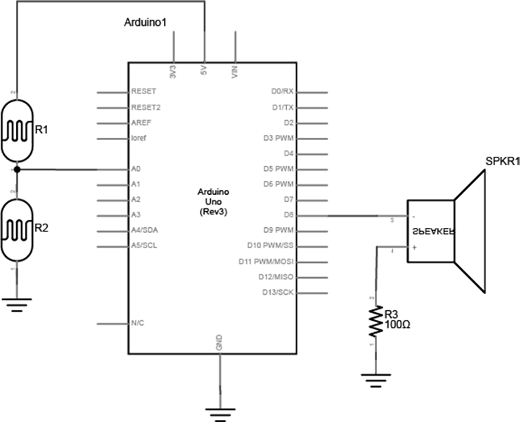
NOTE - this is not the typical way that you would connect an analog sensor input since there is no fixed resistor. Together, the two photocells act as a voltage divider, and either sensor will affect the changing analog value. If you are using variable resistors that can both go to 0 ohms, you should connect a fixed resistor in series from the junction of the two resistors to the input, to avoid a short.
First, determine your range of input values:
  void setup() {
    // initialize serial communications
  }

  void loop() {
    // read the analog input on A0
    // print it to the serial monitor
  }
Next, map those values to our output to generate a tone. You will be using the tone() function.
  // declare int variable to store sensorReading
  // declare float variable for our frequency value

  void setup() {
    // initialize serial communications
  }

  void loop(){}
    // read the analog input on A0, set sensorReading to this value
    // print it to the serial monitor

    // map sensorReading to a an output between 100 and 1000, set frequency to this

    //change the pitch, play for 10ms - use tone()
  }
Upload the code and move your hands over the photocells, listening carefully to the frequency change. It will change from 100 Hz to 1000 HZ, because that’s what you set in the map() command. If you want to change the frequency range, change those two numbers. See if you can get it to play a little tune.
I encourage you to take it a bit further and see if you can play a little tune. You can look up frequency values and save those to an array, then iterate through the array as the input changes. Or, set a specific input range to a particular tone, maybe a scale.
Blog Response
Thoroughly document each part of your lab and post it to your blog with written explanations of what you did. Document your lab in a step-by-step format and please focus on taking informative and clear photos! Be sure to include photos, schematics and videos of each part of the lab.
Submit a link to your post on Canvas.