H-Bridge
How your H-bridge works
The L293NE/SN754410 is a very basic H-bridge. It has two bridges, one on the left side of the chip and one on the right, and can control 2 motors. It can drive up to 1 amp of current, and operate between 4.5V and 36V.
The H-bridge has the following pins and features:
- Pin 1 (1,2EN) enables and disables our motor whether it is give HIGH or LOW
- Pin 2 (1A) is a logic pin for our motor (input is either HIGH or LOW)
- Pin 3 (1Y) is for one of the motor terminals
- Pin 4-5 are for ground
- Pin 6 (2Y) is for the other motor terminal
- Pin 7 (2A) is a logic pin for our motor (input is either HIGH or LOW)
- Pin 8 (VCC2) is the power supply for our motor, this should be given the rated voltage of your motor
- Pin 9-11 are unconnected as you are only using one motor in this lab
- Pin 12-13 are for ground
- Pin 14-15 are unconnected
- Pin 16 (VCC1) is connected to 5V
Below is a diagram of the H-bridge and which pins do what in our example. Included with the diagram is a truth table indicating how the motor will function according to the state of the logic pins (which are set by our Arduino).
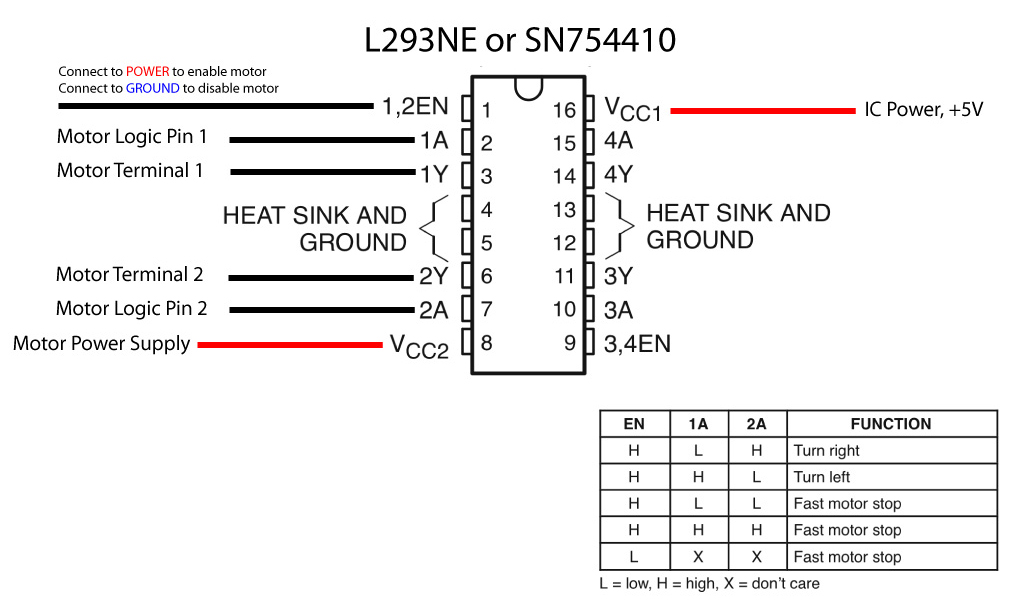
For this lab, both enable pins are connected to 5V to keep them HIGH all the time so the bridge is constantly enabled. The motor logic pins also connected to designated digital pins on your Arduino so you can send them HIGH and LOW control the stepper. The motor supply voltage connects to the voltage source for the motor, an external 12V DC power supply. Not all steppers run on 12V, but the one used for this example does. Check your stepper’s ratings before you power the H-bridge.