BLDG61 Electronics Workshop
Boulder, Colorado
In this special workshop for Bike Week, participants will learn to program, assemble, and solder their own custom made LED bike light. This hands-on session will be an opportunity to learn how to build an interactive circuit from scratch using an ATtiny85 and Neopixel LEDs. The workshop focuses on building skills in hardware, software, and fabrication.
Programming the ATtiny85
The ATtiny85 is a simple, small integrated circuit that works with the Arduino programming environment. In order to program the chip, we will be using a really helpful USB board by Sparkfun called the Tiny AVR Programmer.
Sparkfun’s website has really detailed instructions about working with the ATtiny and the AVR Programmer board. In particular, their steps about installing the drivers and programming the ATtiny in Arduino are very helpful.
Once you have the library installed, be sure you have configured the Arduino settings correctly. Select your board, processor, clock and programmer to the settings in the image below. Unlike with many Arduino boards, you do not need to set your port.
DO NOT set your clock to any external settings, this could permanently damage your chip

Below is the code for programming the board. This program uses the Neopixel library to cycle through a variety of modes and color sequences.
Click here to download a .ino file with the code
#include <Adafruit_NeoPixel.h>
#ifdef __AVR__
  #include <avr/power.h>
#endif

//neopixels are connected to digital 3, which is pin 2 on the ATtiny IC
#define PIN 3
#define NUM_LEDS 4 //number of leds

Adafruit_NeoPixel strip = Adafruit_NeoPixel(NUM_LEDS, PIN, NEO_GRB + NEO_KHZ800);

void setup() {
  //this code block is really important!!
  //we need to be sure the clock is set to 8MHz
  #if defined (__AVR_ATtiny85__)
    if (F_CPU == 8000000) clock_prescale_set(clock_div_1);
  #endif

  strip.begin();
  strip.show();  // Initialize all pixels to 'off'
}

void loop() {
  // Some example procedures showing how to display to the pixels:
  colorWipe(strip.Color(255, 0, 0), 50); // Red
  colorWipe(strip.Color(0, 255, 0), 50); // Green
  colorWipe(strip.Color(0, 0, 255), 50); // Blue

  theaterChase(strip.Color(127, 127, 127), 50); // White
  theaterChase(strip.Color(127, 0, 0), 50); // Red
  theaterChase(strip.Color(0, 0, 127), 50); // Blue

  rainbow(20);
  rainbowCycle(20);
  theaterChaseRainbow(50);
}

// Fill the dots one after the other with a color
void colorWipe(uint32_t c, uint8_t wait) {
  for(uint16_t i=0; i<strip.numPixels(); i++) {
    strip.setPixelColor(i, c);
    strip.show();
    delay(wait);
  }
}

void rainbow(uint8_t wait) {
  uint16_t i, j;

  for(j=0; j<256; j++) {
    for(i=0; i<strip.numPixels(); i++) {
      strip.setPixelColor(i, Wheel((i+j) & 255));
    }
    strip.show();
    delay(wait);
  }
}

// Slightly different, this makes the rainbow equally distributed throughout
void rainbowCycle(uint8_t wait) {
  uint16_t i, j;

  for(j=0; j<256*5; j++) { // 5 cycles of all colors on wheel
    for(i=0; i< strip.numPixels(); i++) {
      strip.setPixelColor(i, Wheel(((i * 256 / strip.numPixels()) + j) & 255));
    }
    strip.show();
    delay(wait);
  }
}

//Theatre-style crawling lights.
void theaterChase(uint32_t c, uint8_t wait) {
  for (int j=0; j<10; j++) {  //do 10 cycles of chasing
    for (int q=0; q < 3; q++) {
      for (uint16_t i=0; i < strip.numPixels(); i=i+3) {
        strip.setPixelColor(i+q, c);    //turn every third pixel on
      }
      strip.show();

      delay(wait);

      for (uint16_t i=0; i < strip.numPixels(); i=i+3) {
        strip.setPixelColor(i+q, 0);        //turn every third pixel off
      }
    }
  }
}

//Theatre-style crawling lights with rainbow effect
void theaterChaseRainbow(uint8_t wait) {
  for (int j=0; j < 256; j++) {     // cycle all 256 colors in the wheel
    for (int q=0; q < 3; q++) {
      for (uint16_t i=0; i < strip.numPixels(); i=i+3) {
        strip.setPixelColor(i+q, Wheel( (i+j) % 255));    //turn every third pixel on
      }
      strip.show();

      delay(wait);

      for (uint16_t i=0; i < strip.numPixels(); i=i+3) {
        strip.setPixelColor(i+q, 0);        //turn every third pixel off
      }
    }
  }
}

// Input a value 0 to 255 to get a color value.
// The colours are a transition r - g - b - back to r.
uint32_t Wheel(byte WheelPos) {
  WheelPos = 255 - WheelPos;
  if(WheelPos < 85) {
    return strip.Color(255 - WheelPos * 3, 0, WheelPos * 3);
  }
  if(WheelPos < 170) {
    WheelPos -= 85;
    return strip.Color(0, WheelPos * 3, 255 - WheelPos * 3);
  }
  WheelPos -= 170;
  return strip.Color(WheelPos * 3, 255 - WheelPos * 3, 0);
}
The ATtiny has 8 pins, they are designated as follows:

Assembly Instructions
Step 1: Add DIP Socket
The DIP Socket will hold our 8-pin ATtiny chip, we’ll add it to the circuit once everything has been soldered. Be sure to position the socket so that the notch at the top is closest to the end of the prototyping board.

Step 2: Add 2 Resistors
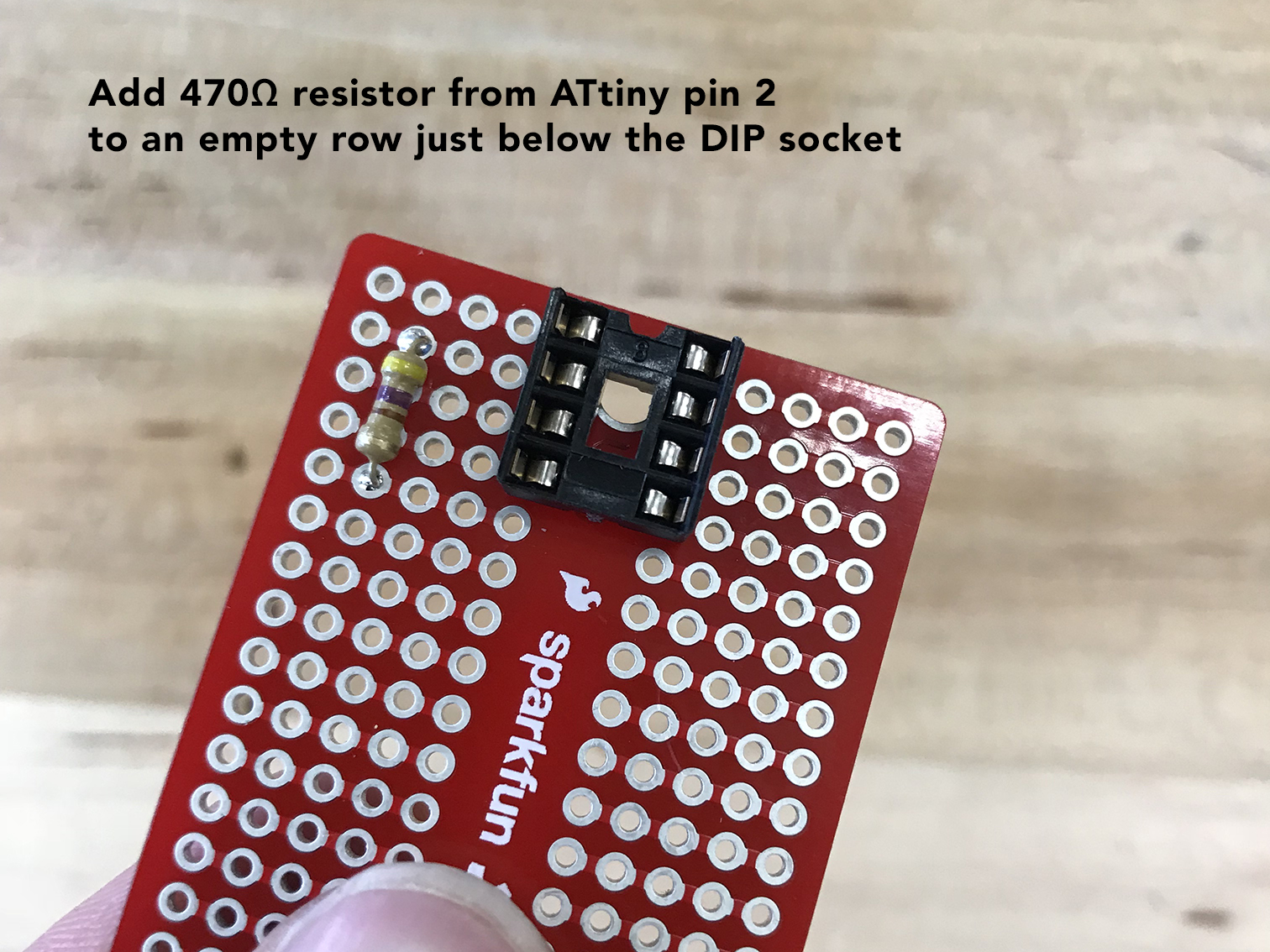
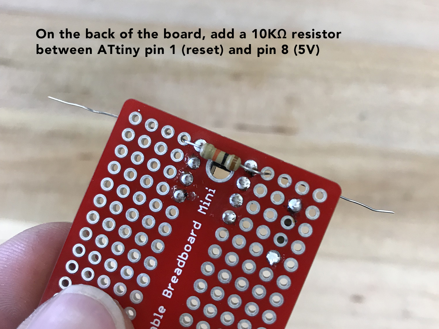
You will be adding 2 resistors, one is 470Ω for the neopixel strip and connects to pin 2 on the ATtiny. The other is 10KΩ and connects between pin 1 (reset) and pin 8 (5V) on the ATtiny.
Trim the leads after soldering them to the board.

Step 3: Add Capacitor
Next, add a 100uF capacitor between pin 4 (GND) and pin 8 (5V) of the ATtiny. Bending the leads 90 degrees allows the capacitor to lay flat against the board.


Solder the two leads of the capacitor on the back of the board:

Trim the capacitor wires. Then, cut two wires to connect the capacitor to ATtiny pins.


Step 4: Add Battery Holder
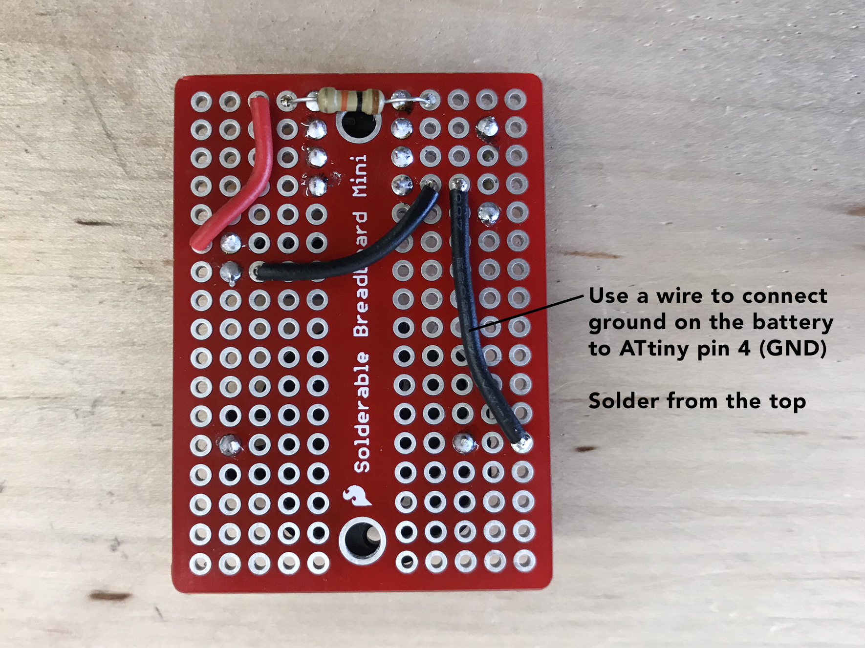
Add the battery holder. Be sure to position it so that the positive side of the battery holder is on the same side of the board as ATtiny pins 5,6,7,8. Solder the battery on the back of the board. You will also add a wire connecting the ground pin of the battery holder to pin 4 (GND) on the ATtiny.

Step 5: Solder Wires to Switch & Neopixels
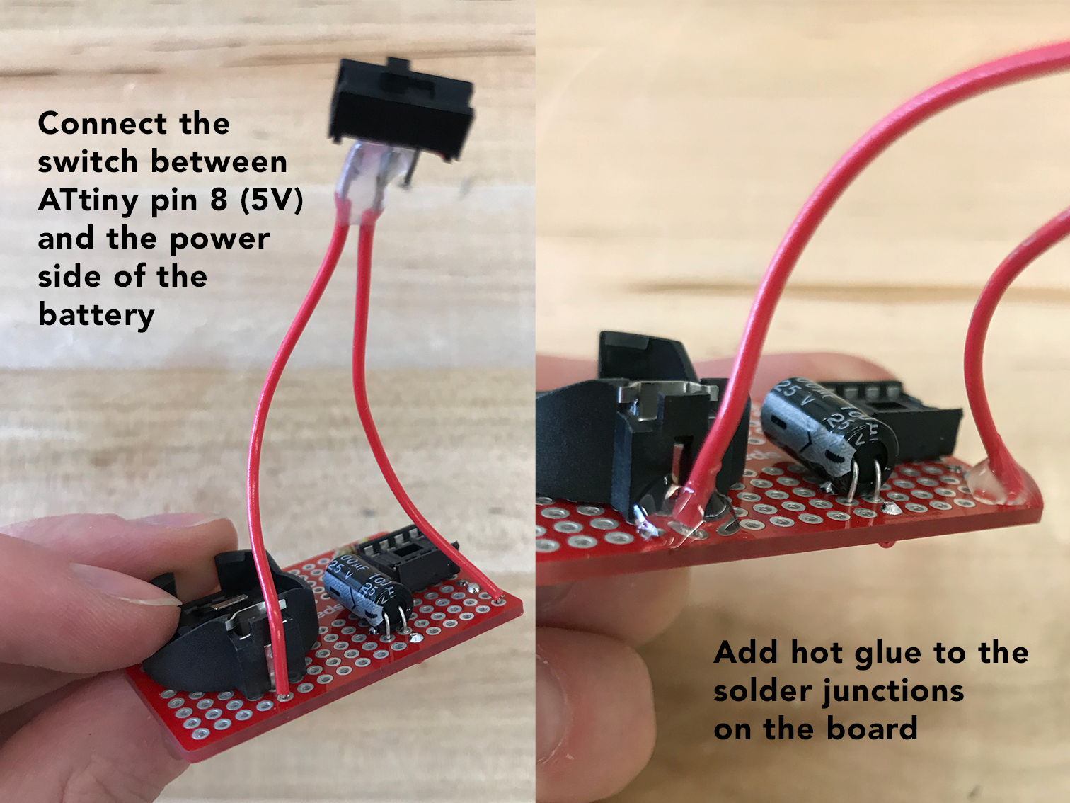
For both the switch and the neopixels, you will be attaching wires that will allow the components to be detached from the board.
A great trick for this is to first add solder to the place you intend to create a connection. Then, remove the solder and pick up your wire and slide the wire into the hot solder.


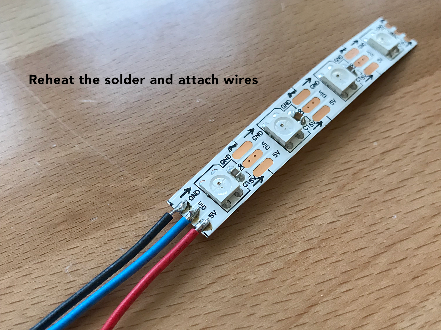
To ensure that the solder connections don’t break, it’s helpful to add a dab of hot glue to the junction point.

Next, connect the switch between the positive side of the battery and pin 8 (5V) on the ATtiny.
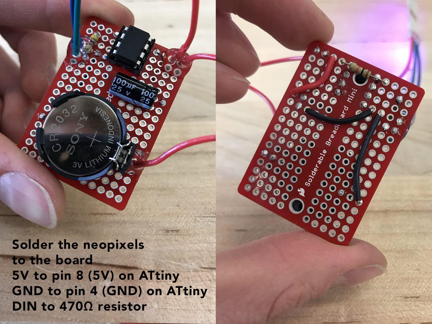
Finally, solder the neopixel wires to your board.
Step 6: Add Battery & Programmed ATtiny
Put it all together and admire your creation!
